

Failure Modes in Flex Circuit PCBs
Rigid-flex circuit boards have become commonplace across many industries due to their reliability, flexibility and compact design. However, as with any product that must be manufactured and used in a challenging environment, these PCBs can sometimes experience failure. Understanding the most common failure modes in flex circuits is critical for manufacturers, engineers and designers seeking to avoid these risks and ensure optimal performance and longevity. Mechanical stress, thermal stress, chemical and environmental factors, electrical overstress and ESD are the main threats to a rigid-flex circuit’s quality and function.
Mechanical stress is caused by handling, mishandling or bending a rigid flex circuit beyond its maximum bending capabilities. This can cause traces to fracture or crack, and it is especially dangerous for delicate components like those in touchscreens. In order to minimize this risk, a flex circuit should have a minimum bend radius of 100 microns and use rounded corners in the copper trace arrangement. In addition, a protective epoxy bead should be placed at the corner where a rigid area transitions into the flex area to prevent it from kinking.
Rigid flex circuit pcb are exposed to many different chemicals, environmental conditions and power surges throughout their lifetime. These factors can lead to the degradation of the materials that comprise the board, which in turn can negatively impact performance and longevity. For example, copper-rich surfaces can be susceptible to corrosion from a range of chemicals, and exposure to high temperatures can erode the glass-resin bonding that holds the circuit together.
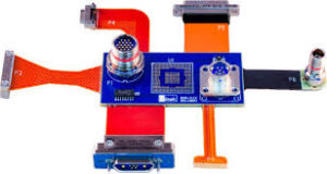
Common Failure Modes in Flex Circuit PCBs
Rigid-flex PCBs operate in various temperature environments, resulting in them being subject to thermal stresses. These stresses can lead to delamination, solder joint problems and connections, and other structural and electrical issues. To minimize this threat, a rigid-flex circuit should be rated for its expected number of thermal cycles and designed with thermal management features such as heat sinks and controlled impedance traces to help distribute the board’s thermal load evenly.
Among the most dangerous and costly of all flex circuit failures, electrical overstress can result in burned components and melted traces. This problem can be caused by improper design, overcurrents or sudden voltage spikes, which can lead to charring or melting of components on the circuit board. Additionally, electrostatic discharge (ESD) can result in broken components and irreversible damage to sensitive electronic devices.
ESD-related damage is often invisible to the naked eye and requires specialized laboratory testing to identify. This involves a complex combination of engineering analysis, high magnification photography and formal problem-solving methodology.
Fortunately, these and other common failure modes can be prevented by careful attention to PCB design, manufacturing and assembly processes. By implementing proper design considerations, materials selection and assembly techniques, manufacturers and designers can significantly improve the longevity and operational efficiency of their rigid-flex circuit boards. By proactively addressing these potential risks, they can protect their products from premature failure and costly rework and replacement costs.
